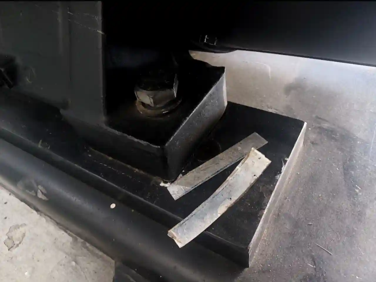
Improper shim installation found under motor foot during laser alignment
Improper shim installation identified during laser alignment inspection of a hospital pump motor in the UAE.

The image shows two separate shim pieces improperly installed beneath the motor foot. The split and uneven shim arrangement can reduce proper contact between the motor foot and foundation, resulting in unstable support, uneven load distribution, and potential alignment problems. This improper shimming condition can contribute to increased motor vibration during operation.

Improper Shim Installation: Hidden Alignment Problem in a Hospital Pump Motor

Case Study: Improper Shims Found During Laser Alignment of a 24/7 Hospital Pump

There is a need for high reliability of equipment in a hospital pump room since important pumps work all the time to provide basic services in the building. Our company was contacted by a hospital in the UAE to solve the problem with a motor that was frequently vibrating. Although the motor bearings had already been changed by the maintenance staff, the problem persisted. They were replaced again but the vibration problem still occurred. Then, the maintenance staff assumed that the misalignment of the pump-motor shaft was causing the problem and asked for a professional laser alignment inspection. During our inspection, we found out that there was a misalignment problem and also the wrong installation of shims on the motor feet. The problem was solved by correctly installing shims and getting the right alignment of the pump-motor shaft.

The Maintenance Problem
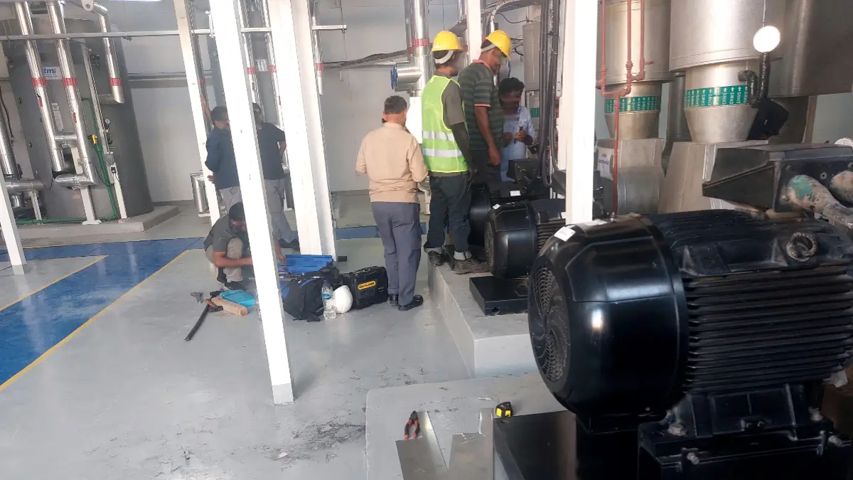
Technicians inspecting a hospital pump motor during laser alignment and maintenance
Technicians inspecting the pump motor during the laser alignment assessment.

Maintenance technicians reviewing the pump motor and alignment condition during the inspection, as part of the investigation into an improper shim installation and related vibration problem.

The motor was placed in a pump room of a hospital and the need for constant operation was there. Hence, reliability of the equipment was highly critical. A vibration issue was reported by the maintenance personnel.

During their troubleshooting and maintenance process:

– Motor bearings were replaced.
– Vibration in the motor was observed.
– Again, the bearings were replaced.
– Even then, vibration was an issue.

Since the problem of vibration did not get solved due to bearing replacement, the possibility of shaft misalignment was considered by the maintenance crew. Our team was summoned for the alignment of the pump and motor using laser alignment.

Laser Shaft Alignment Inspection

Pump and motor shaft alignment were evaluated. A misalignment was detected using laser measurement of the pump and motor shafts. But the evaluation process was not limited to only the shafts. Motor shaft alignment was also tested. While testing motor shaft alignment, we discovered that the wrong shims had been put underneath the motor feet. It was important to detect this as shims are a crucial part of the mechanical foundation of a motor.

The Improper Shim Installation

Two improperly installed shim pieces positioned under a motor foot, creating uneven support that can contribute to vibration.
Two improperly installed shim pieces under the motor foot can create uneven support and contribute to excessive vibration.

The image shows two separate shim pieces improperly installed beneath the motor foot. The split and uneven shim arrangement can reduce proper contact between the motor foot and foundation, resulting in unstable support, uneven load distribution, and potential alignment problems. This improper shimming condition can contribute to increased motor vibration during operation.

The motor had shims placed below its feet; however, the arrangement of the shims was inappropriate for precision alignment installation. The improper placement of the shims may cause trouble even if the readings of the alignment were within tolerance at one moment in time.

For instance, problems might happen due to the following reasons:

– Shims do not support the motor properly.
– Shims are not placed appropriately beneath the motor foot.
– Several shims are not in proper contact.
– Shims are damaged, bent, contaminated, or uneven.
– The motor foot is not supported appropriately.
– The arrangement of the shims changes during the process of mounting.

The laser alignment reading could be adjusted by changing the position of the motor, but the mounting of the motor should be appropriate too.

Why Correct Shimming Matters

Shimming should not be done only to get a certain alignment number. The motor needs a steady and well-supported mounting position. In case the shims are improperly mounted, the mounting position of the motor will be unstable. This may influence the end result of the alignment process and may cause mechanical difficulties. The motor may be in proper alignment at the first measurement, but when the mounting position is not properly supported, it may change after tightening or usage. Therefore, mounting of the shims is an important part of shaft alignment process.

Corrective Action
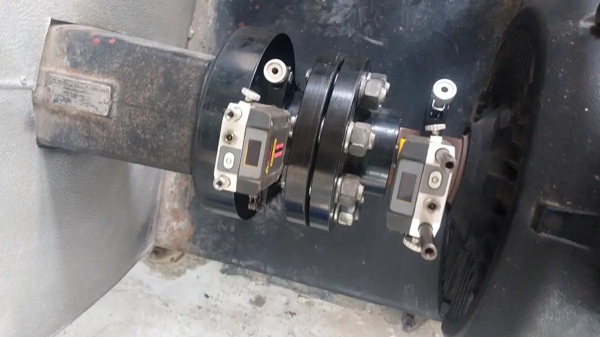
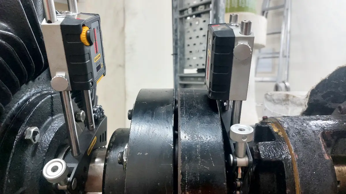
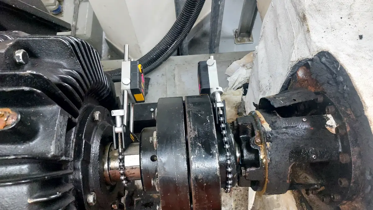
Laser alignment system installed on a hospital pump motor shaft to inspect alignment
Laser alignment system installed on the pump motor shaft for precision alignment inspection.

Laser alignment equipment installed on the pump motor shaft during inspection to identify possible shaft alignment and installation issues.

Following the detection of the wrong placement of the shims, the problem of the motor mounting was sorted out. The old shim setup was examined and changed if necessary to ensure correct support of the motor feet. Then the motor was mounted and the alignment between the pump and the motor shafts was adjusted using the laser alignment.

Both:

– Vertical alignment
– Horizontal alignment

were checked and adjusted.

Following the adjustments, the alignment was checked again.

Final Alignment Result

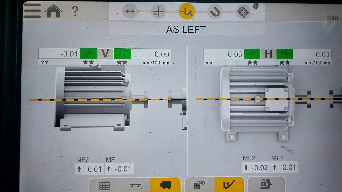
The last pump and motor alignment was done to meet the tolerance requirement of the client. The motor mount problem was also solved by using the right shimming technique. This gave the equipment a stable platform for the final alignment instead of using the wrong shimming technique. The last laser alignment readings were taken.

Why Repeated Bearing Replacement Should Trigger Further Investigation

Continuous replacement of the bearings without determining the cause may prove to be costly and ineffective. There are various factors that may cause the failure or early wear of the bearing, such as:

– Misalignment
– Lubrication failure
– Overloading
– Imbalance
– Installation problem
– Contamination
– Electrical failure
– Foundation problem
– Operating condition

Hence, by continuously replacing the bearing, it is not necessary that the root cause will be solved. In this case, the maintenance department rightly thought about alignment as a possibility and asked for laser alignment testing. The test indicated a shaft alignment problem and also a problem in the installation of shims.

Important Lesson for 24/7 Pump Systems

The continuous operation of a pump motor within a hospital setting must be viewed as a critical rotating machine. In the case of a critical rotating machine, alignment is not a single event. Following its installation, major maintenance, bearing change, coupling change, or any other mechanical repair, the alignment of the pump motor needs to be checked based on the maintenance criteria of the site. A correct alignment record will also aid in comparison for future measurements.

Proper Shim Installation and Laser Alignment Service Must Work Together
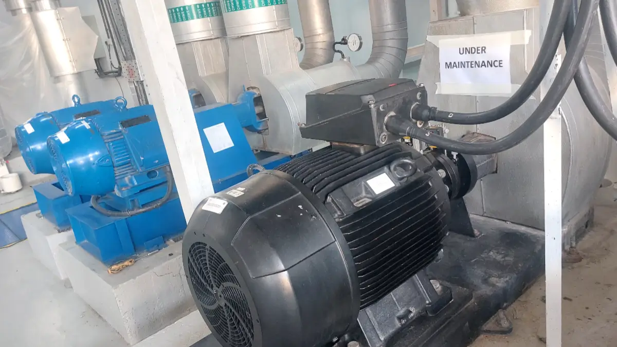
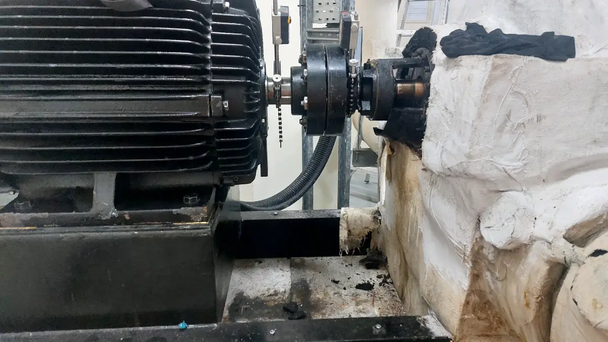
Laser alignment system installed between hospital pump and motor during maintenance inspection
Pump and motor under maintenance with the laser alignment system installed for alignment inspection.

Hospital pump and motor assembly under maintenance, with the laser alignment system mounted on the shaft to check alignment conditions before corrective work. Precision laser alignment and correct mechanical mounting have a strong link. The laser system is able to determine the exact shaft position and find out how much correction should be applied. But the correction needs to be made with an appropriate mounting.

This means:

Measuring → Checking the mounting → Adjusting the shims → Alignment → Rechecking

And not:

Measuring → Randomly adding shims → Alignment

The goal here is to reach:

1. Correct shaft alignment.
2. Appropriate motor mounting.

Conclusion

We were summoned to a hospital pump room in UAE where the maintenance crew was facing problems related to motor vibration. The motor bearings had already been changed multiple times but the vibration issues persisted. It was assumed by the maintenance crew that shaft misalignment might be the cause of such problems, and hence a laser alignment check was requested.

Upon checking, it was found that there was an issue with pump motor misalignment as well as shims being placed incorrectly under the feet of the motor. The motor installation was corrected using correct shims and shaft alignment between pump and motor was corrected horizontally as well as vertically.

Key Takeaway

Shaft alignment being correct does not matter if the motor is resting on wrongly installed shims.

The motor may be aligned using a laser alignment tool, but the stability of the shims could affect the accuracy of the installation process. It is always advisable to check the motor mounting, shimming, and shaft alignment in critical 24-hour pumping systems. If the bearings keep failing or the machine vibrates even after replacing the bearings, do not keep replacing the parts without analyzing the mechanical situation.

Establish the problem, fix the mounting, do the laser alignment, and then analyze the situation.
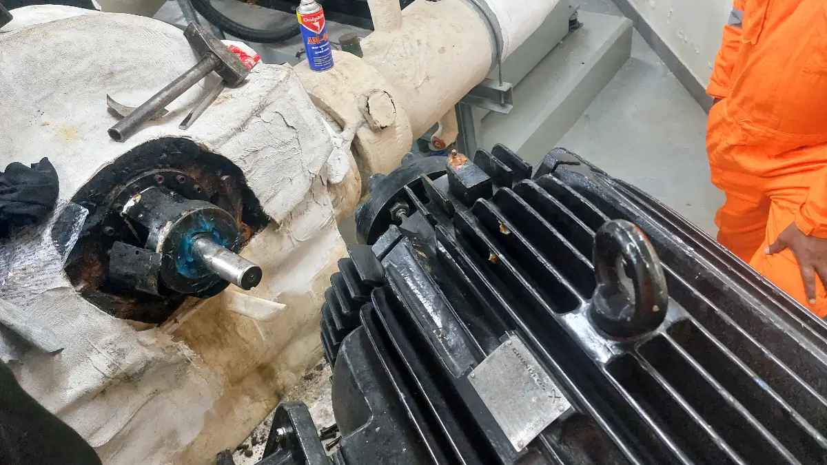
Pump before laser alignment after bearing replacement
Pump bearing replacement completed before laser shaft alignment.

Pump and motor assembly shown after bearing replacement and before laser alignment. Proper alignment should be performed before returning the pump to operation to help prevent vibration, premature bearing wear, coupling damage, and equipment failure.

Don’t Run a Pump Motor After Bearing Replacement Without Laser Alignment

Case Study: Shim Correction Required After Pump Bearing Replacement

Though replacing a pump bearing seems to be a simple job for maintenance personnel, it may have an influence on the final shaft alignment and the interaction between the pump and motor. In the event of pump bearing replacement, it is not enough to mount the motor, fix it and use the machine without shaft alignment check.

In this particular case, the pump bearing replacement was done by another company for our customer. After bearing replacement, it was necessary to mount and align the motor with the pump. Our company was contacted to do laser shaft alignment before the operation of the pump-motor combination. During the alignment inspection, we noticed a discrepancy of 0.2 mm in shim setting under the motor feet after tightening all the bolts of both the pump and the motor bases.

The Situation

The pump bearing had been replaced as part of the client’s maintenance work. After the bearing replacement was completed, the motor was ready for installation and coupling alignment. Instead of starting the equipment immediately after mechanical assembly, the client arranged for a professional laser alignment check. Our team carried out the laser shaft alignment between the pump and motor. The initial measurements showed that the pump and motor were not within the required alignment tolerance. Both vertical and horizontal alignment conditions were checked and evaluated.

Pump bearing replacement measurement before bolt tightening and laser alignment
Measurement after bearing change and before final bolt tightening ensures accurate pump alignment.

Laser alignment measurements are taken after pump bearing replacement and before final bolt tightening. Checking alignment at this stage helps identify shaft or foot movement and supports accurate pump motor alignment for reliable operation.

Alignment Inspection

The first thing to do was to determine the real shaft alignment situation when the pump and motor mounting bolts were tight. This is because an alignment check done without ensuring that the mounting bolts have been properly tightened may not give the right alignment situation of the machine. When all the pump and motor base bolts were properly tightened, it was found out that the alignment needed further correction.

Pump bearing replacement bolt tightening and horizontal laser alignment adjustment
Bolt tightening and horizontal adjustment during pump laser alignment after bearing replacement.

A pump and motor are being adjusted during laser alignment after a bearing change. Controlled bolt tightening and horizontal adjustment help maintain shaft alignment, reduce vibration, and prevent premature bearing and coupling wear.

During the inspection, it was discovered that there was 0.2mm correction in shims for the motor feet. This means that the motor cannot just be placed in its place and considered aligned. It had to be done through a controlled shim correction.

The 0.2 mm Shim Correction

Based on the laser alignment measurements, a 0.2 mm shim correction was added at the required motor feet. After installing the required shim correction, the motor was repositioned for horizontal alignment and the alignment was measured again. The horizontal and vertical alignment conditions were then corrected. A final laser measurement was carried out to confirm the result. The final alignment was achieved within the client’s required tolerance.

Why Alignment Was Required After Bearing Replacement

Laser alignment in progress after pump bearing replacement
Laser alignment in progress to verify accurate pump and motor shaft alignment after bearing replacement.

Laser shaft alignment is in progress on a pump and motor following bearing replacement. Precision laser measurements help correct horizontal and vertical misalignment, reduce vibration, and support reliable pump operation.

During the inspection, it was discovered that there was 0.2mm correction in shims for the motor feet. This means that the motor cannot just be placed in its place and considered aligned. It had to be done through a controlled shim correction.

Replacement of pump bearings may result in alteration in the position of the rotating shaft in relation to the pump housing and other connected equipment. Even if the process of replacing the bearing itself is done properly, it cannot be presumed that the final position of the pump shaft is the same as it was before.

Some other factors which affect the final alignment include:

– Bearing mounting
– Bearing seating
– Pump shaft position
– Condition of pump housing
– Mounting and assembly of the components
– Existing shims
– Condition of base
– Bolt tightening
– Thermal and mechanical considerations

Hence, the previous alignment condition cannot be taken for granted even after major pump repair.

What Could Happen If Alignment Is Skipped?

Operating a pump and motor without checking the shaft alignment could lead to unnecessary mechanical issues.

Misalignment might cause:

– Wear on couplings
– Loading on bearings
– Vibrations
– Mechanical stresses
– Premature bearing failure
– Seal failures
– Damage to couplings
– Decreased reliability of the equipment
– Unscheduled maintenance

The equipment could be operational after installation, but operation does not mean that the machine is properly aligned. The machine could be operational even though it has a misalignment problem that decreases the lifespan of bearings, couplings, or seals.

Laser Alignment Before Commissioning

Laser measurement in progress for pump shaft alignment after bearing replacement
Laser measurement in progress to verify pump and motor shaft alignment after bearing replacement.

Precision laser measurement is in progress on the pump and motor shaft after bearing replacement. The measurements help identify and correct shaft misalignment, supporting accurate alignment, reduced vibration, and reliable pump operation.

In this example, the laser alignment test revealed a correction that would otherwise have gone undetected. The needed correction was about 0.2 mm at the motor mount points Following the correction, the alignment of the pump and motor shafts fell within the specified tolerances by the client. This is an illustration of the need to consider laser alignment as part of the commissioning process after replacing pump bearings.

Final Result

Final-Alignment
Final-Alignment.

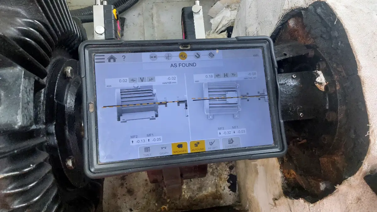
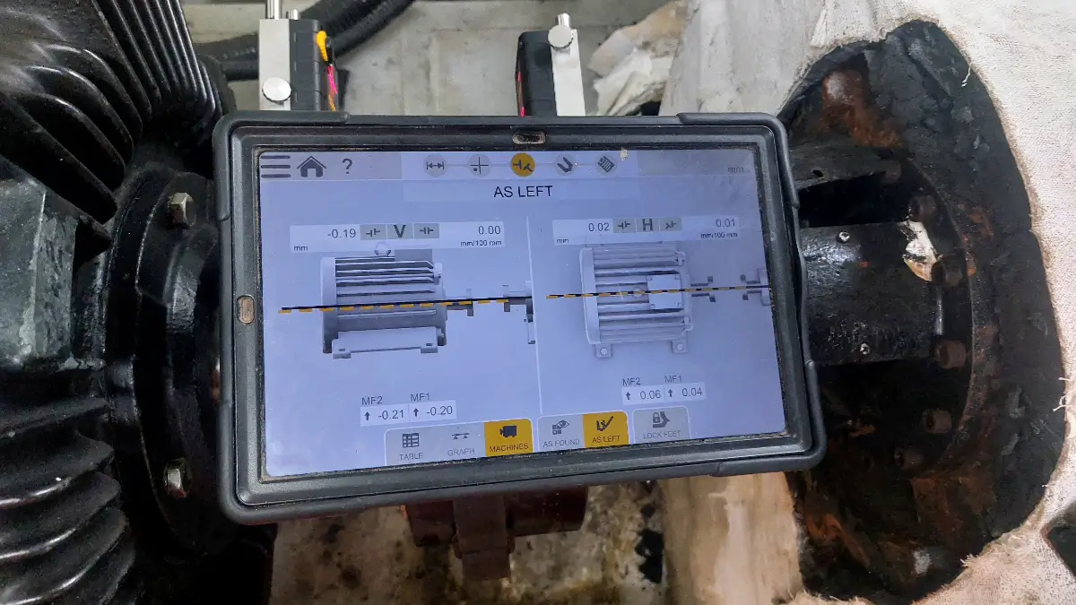
Image showing the tolerance of after alignment.

After the required shim correction was installed:

Initial condition:

– Pump bearing replaced
– Motor ready for installation
– Alignment outside the required tolerance
– Approximately 0.2 mm shim correction identified

Corrective action:

– Required shim correction added
– Motor position corrected
– Horizontal alignment corrected
– Vertical alignment corrected
– Final laser measurement performed

Final condition:

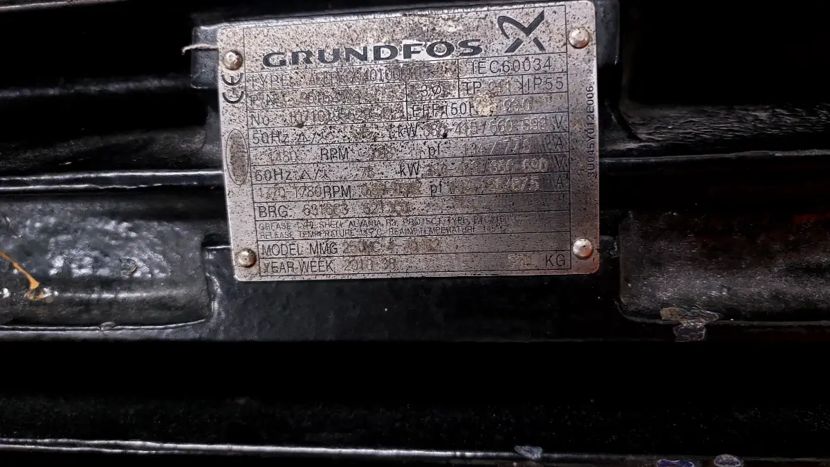
Motor nameplate of pump motor after laser alignment
Motor nameplate of the pump motor where laser alignment was completed after bearing replacement.

Motor nameplate shown for the pump motor that underwent laser shaft alignment service after bearing replacement. The nameplate provides the motor’s key identification and technical specifications.

– Pump and motor alignment achieved within the client’s required tolerance
– Equipment ready for operation following completion of the required mechanical checks

Key Lesson

Do Not Assume Previous Alignment to Be Correct. One of the most important takeaways from this case study is very simple:

After pump bearing replacement, do not assume that the pump-motor alignment remains correct. The replacement of the bearing and following mechanical work may alter the final position of the shaft. Laser alignment test gives you a precise measurement of the alignment between the pump and motor and not the assumption. In our particular case, the laser alignment test revealed that a correction of 0.2 mm shim was needed to meet the customer’s tolerance for alignment.

Our Recommendation

Replacement of a pump bearing always requires that the following procedure should be followed before the machine can be put back into operation:

1. Complete the pump bearing replacement.
2. Reinstall and secure the pump and motor.
3. Fully tighten the relevant mounting bolts according to the approved procedure.
4. Check the pump-motor shaft alignment using a laser alignment system.
5. Measure both vertical and horizontal alignment.
6. Make the required shim and positional corrections.
7. Recheck the alignment after corrections.
8. Confirm the final readings against the client’s specified tolerance.
9. Complete the final alignment report before commissioning.

Conclusion

Laser alignment after pump bearing replacement to ensure accurate pump motor and shaft alignment
Laser alignment after bearing change helps ensure accurate shaft alignment and reliable pump operation..

A professional laser alignment setup being used after pump bearing replacement to accurately align the pump and motor shafts. Proper laser alignment helps prevent vibration, premature bearing wear, coupling damage, and unexpected pump downtime.

Replacement of the bearings in the pump does not necessarily imply that the maintenance process is complete. The relationship between the pump and motor must be evaluated prior to commissioning the equipment. In this case, the laser shaft alignment examination revealed that there was a need for a correction of approximately 0.2 mm shim on the motor mounting areas. Once the correction had been done, the shaft alignment was brought within the client’s acceptable tolerance.

The case demonstrates a simple but important maintenance principle:

Don’t run a pump motor after bearing replacement without verifying the pump-motor laser alignment.

A few hours spent checking and correcting alignment can help prevent much more expensive problems caused by premature bearing, coupling, seal, and vibration-related failures.

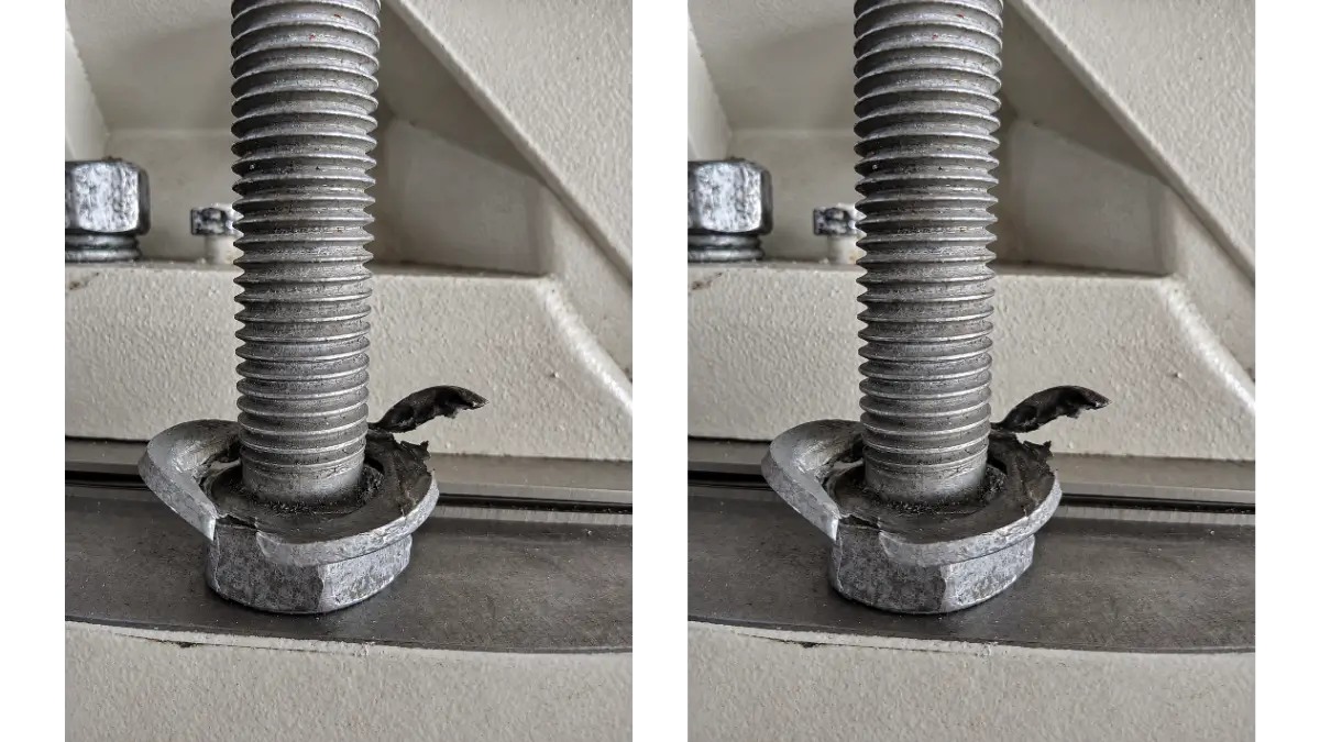
Damaged washer causing soft foot problem during motor pump skid laser alignment
Damaged washer found underneath the motor frame during a motor-pump skid alignment investigation.

This image showing a damaged washer positioned underneath the motor frame. The deformed or damaged washer has affected the support condition of the motor, creating a soft foot condition and potentially influencing the accuracy of the motor-to-pump alignment. The image highlights the physical defect discovered during the alignment investigation and its possible impact on equipment stability and alignment.

Soft Foot Problem in Motor Pump Skid Alignment Caused by a Damaged Washer

Case Study: Hidden Washer Damage Behind Unstable Soft Foot Readings

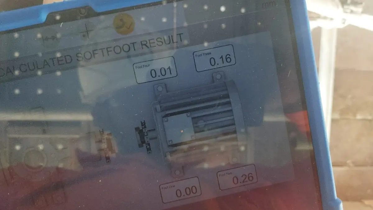
When performing the laser shaft alignment of the motor and pump skid, we experienced difficulties with the soft foot condition. From the first laser alignment test, it turned out that the vertical and horizontal shaft alignment could be aligned according to the allowable values, but the soft foot readings were inconsistent and could not meet the client’s acceptable values at all times. At first, the issue was thought to arise from either the motor base, shimming, or motor mount condition.

This situation proves how important it is to check the motor mount installation (Bolts, Nuts, Washers) prior to the repeated shimming process.

The Soft Foot Problem

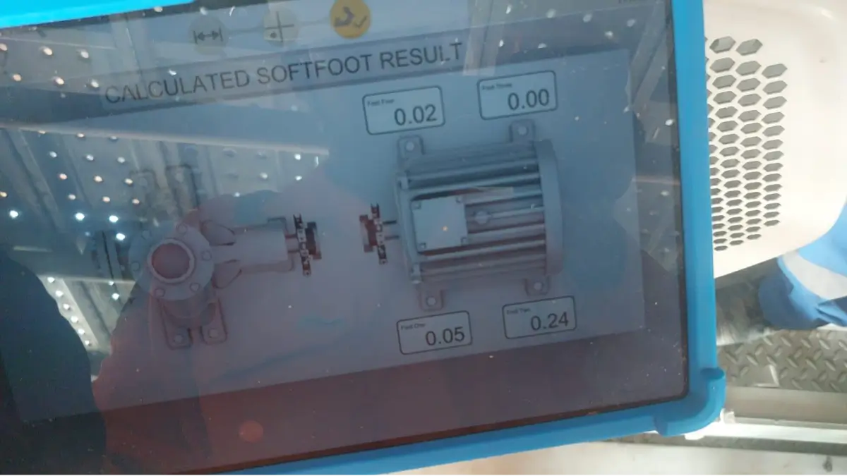
First soft foot measurement showing a changing value during motor pump skid alignment with a damaged shim
First soft foot verification showing the measured value with the damaged shim still installed.

Initial verification of the Soft Foot Problem in Motor Pump Skid Alignment showing the measured soft foot value before correction. The damaged washers beneath the motor foot affected the seating condition and resulted in an abnormal soft foot measurement during the laser alignment process.

The process of aligning the motor pump involved correcting the alignment values both in the vertical and horizontal directions. Following the correction of these alignment values, acceptable values were obtained. However, on checking for soft-foot in the motor foot, the readings were not consistent.

A single motor foot was obtaining varying soft-foot readings in successive measurement attempts.

This presented a serious challenge, as follows:

– The soft-foot readings were inconsistent and not acceptable.
– Measurement in successive attempts was giving varying results.
– Further correction using the addition or removal of shims was not solving the problem.
– Further tampering with the shims could jeopardize the already aligned shaft values.

At this point, just carrying out further correction using shims was not the right solution to adopt.

Investigation of the Motor Base & Nut, Bolt, Washer & Base Frame

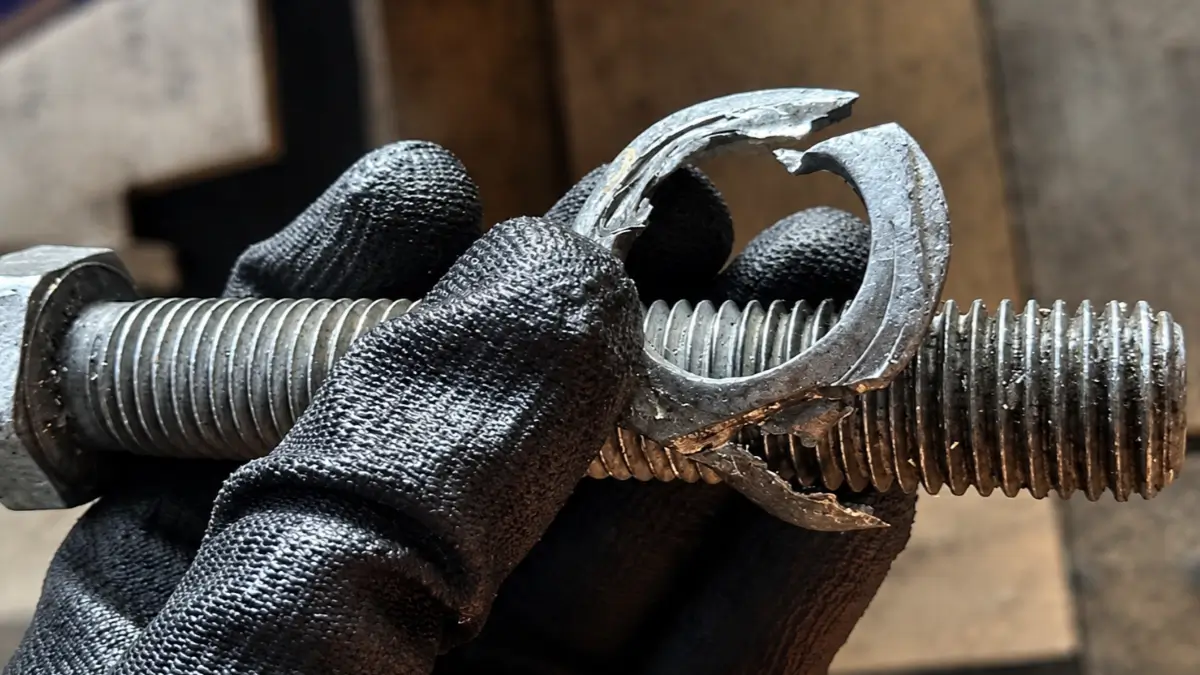
Damaged Bolt Washer Causing Soft Foot
Damaged bolt washer identified beneath the motor frame during the soft foot investigation.

Close-up view of the damaged washer beneath the motor base bolt. The washer deformation affected the seating and support of the motor foot, contributing to the soft foot condition detected during the motor-pump laser alignment.

As the soft-foot values kept fluctuating, we decided to investigate the motor mounting system. In the process of investigation, we noticed a deformed/damaged washer below the motor base. The condition of the washer is shown in the picture.

The washer was deformed and damaged; therefore, the condition of the motor base at the point of mounting was not stable. This was a significant discovery since a reliable reading of soft-foot value is possible only when there is a stable mechanical condition of the motor foot.

Root Cause

The reason why there were irregularities in the soft-foot readings was because of the damaged washer that was located under the motor base. Since the washer was damaged, the seating of the motor mounting point was not stable at all.

Thus, whenever the motor mounting point is affected, and soft foot is taken again, the motor foot can settle differently. That is why different soft-foot readings were acquired. It was not just a case of adding or taking out shims; the mechanical condition of the motor mounting point should have been addressed first.

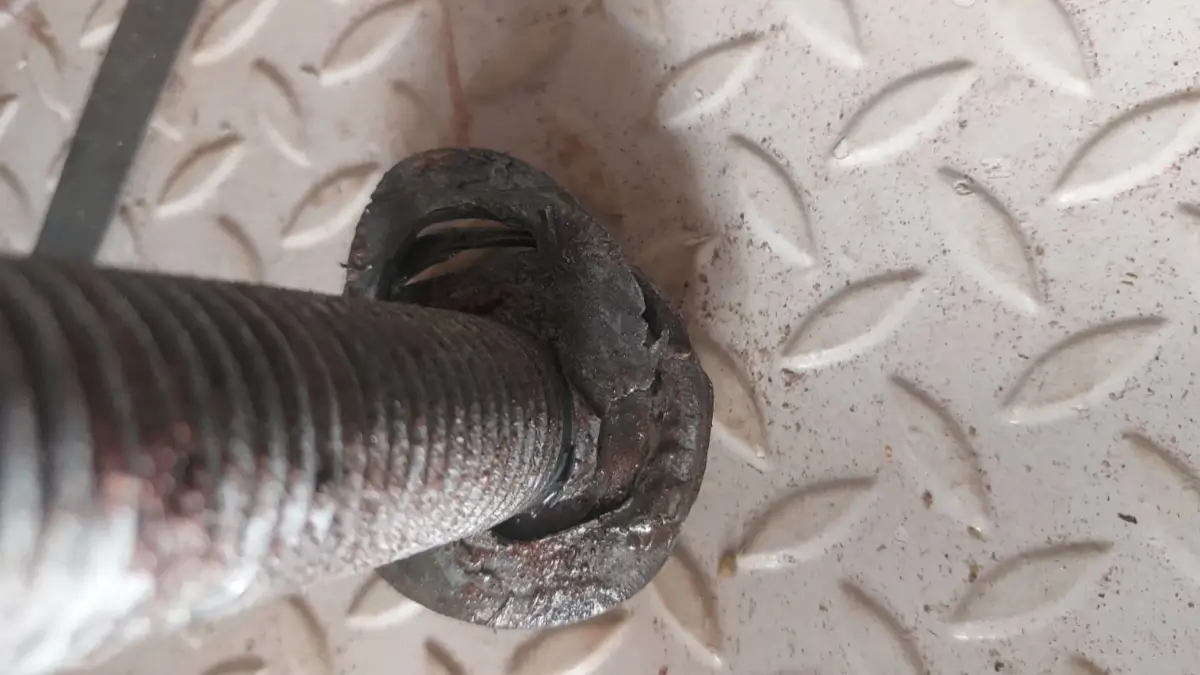
Deformed washer at the motor mounting bolt contributing to soft foot during alignment
Deformed washer found at the motor mounting bolt during the alignment investigation.

The image shows a damaged and deformed washer at the motor mounting point. The improper washer condition reduced the stability and uniform contact of the motor foot, contributing to the observed soft foot condition and affecting the alignment process.

Corrective Action

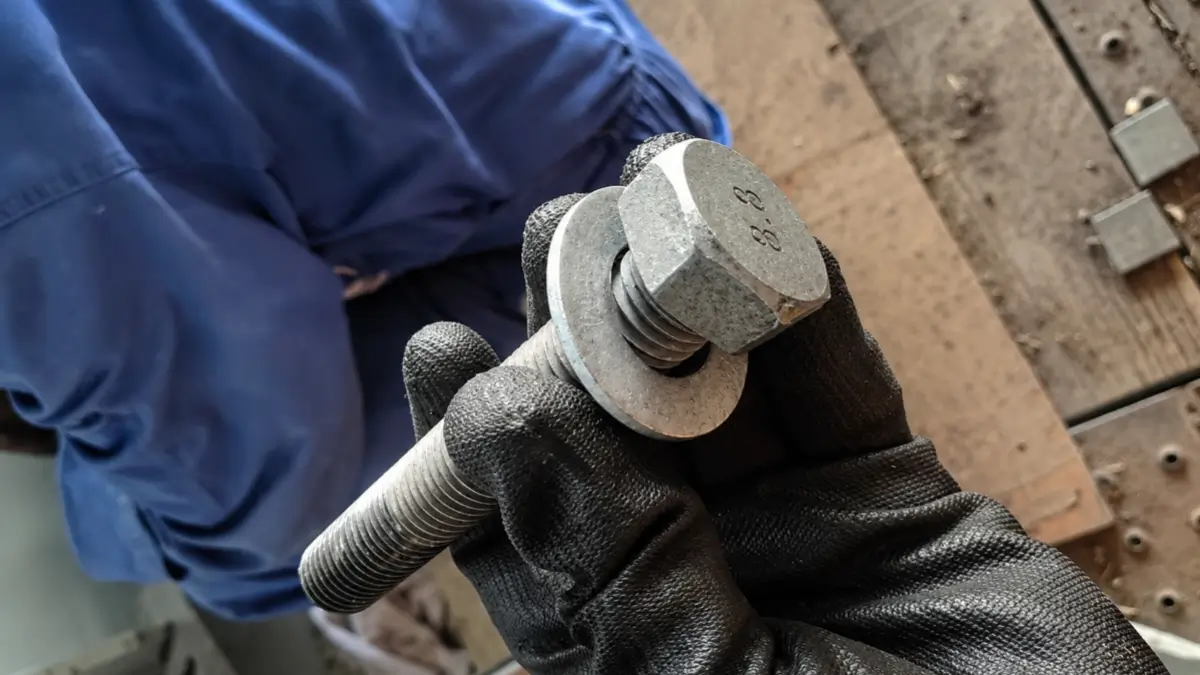
New washer installed beneath the motor frame bolt after replacing the damaged washer
New washer installed at the motor mounting bolt after removal of the damaged washer.

Close-up view showing the damaged washer replaced with a new washer beneath the motor frame bolt. The replacement restored proper support and seating of the motor foot, helping to eliminate the soft foot condition and improve the stability and accuracy of the motor-pump laser alignment.

Soft Foot Verification and Final Alignment

The old washer was removed and replaced by a new washer. The motor mounting was fixed after the installation of the new washer. The soft-foot testing was done again. After the installation of the new washer, the soft-foot readings were found to be constant. After the correction of the soft-foot problem, the laser shaft alignment was done.

Before and After Result

Before Washer Replacement

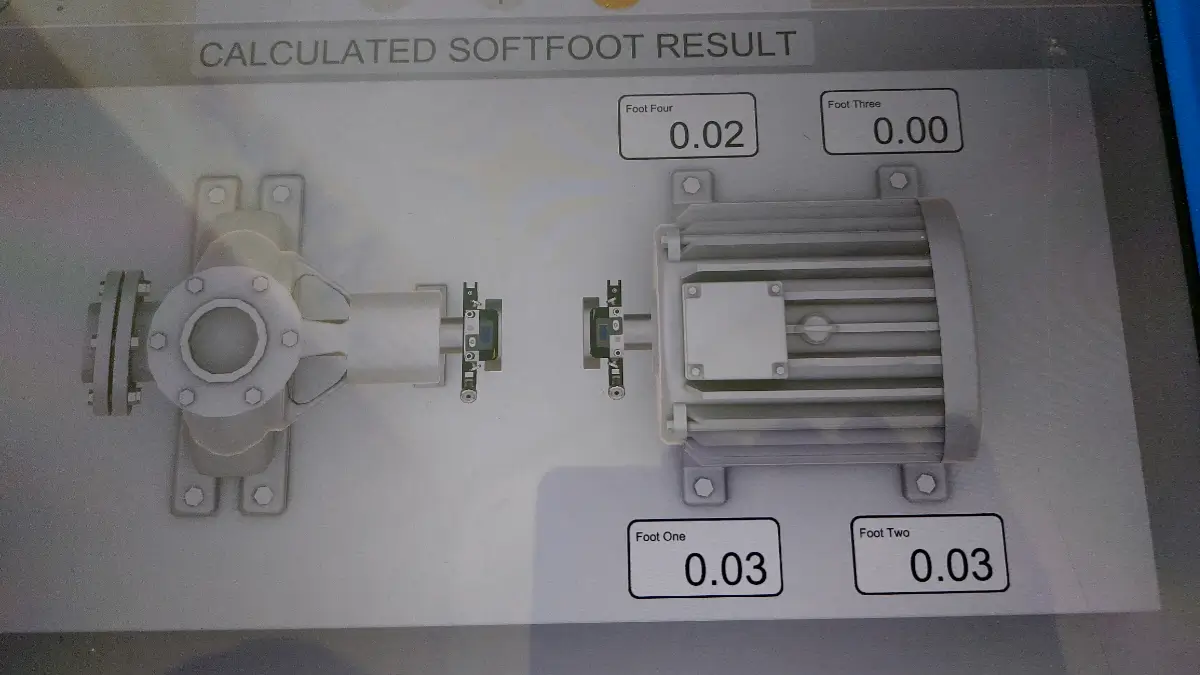
Second soft foot measurement showing a different value with the damaged shim during motor pump skid alignment

Second soft foot verification showing a changed measurement value with the damaged shim still in place.

Second verification of the Soft Foot Problem in Motor Pump Skid Alignment showing a different measured value from the first check. The variation in the soft foot reading indicated an unstable or inconsistent motor foot seating condition, with the damaged shim contributing to the problem during the alignment investigation.

– Soft Foot: Unstable
– Multiple Measurements: Give different results
– Shimming: Has not solved the problem permanently
– Root Cause: The damaged washer under the motor frame

After Washer Replacement

Final soft foot value after replacing the damaged washer during motor pump skid laser alignment

Final soft foot measurement after replacing the damaged washer and correcting the motor mounting condition.

Final soft foot measurement after replacing the damaged washer and correcting the motor mounting condition.

-Motor mount condition: Stable
-Soft-foot values: Uniform
-Soft foot: Adjusted to the client’s specification
-Shaft alignment: Carried out after adjustment of soft foot

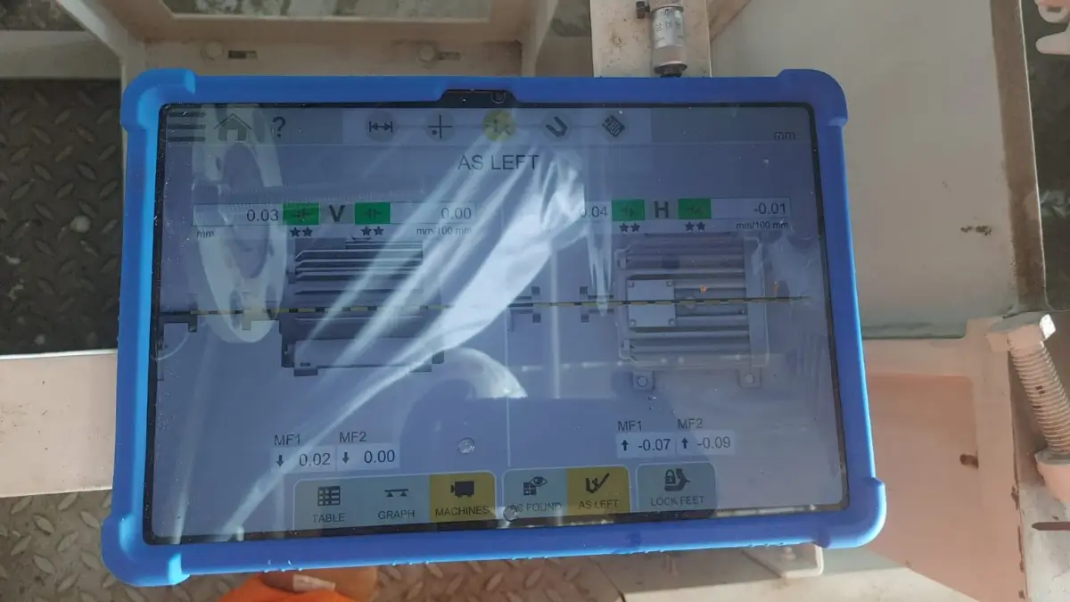
Client-required horizontal and vertical alignment tolerance values for motor pump skid alignment
Client-specified horizontal and vertical alignment tolerance requirements for the motor-pump skid.

Reference image showing the client-required alignment tolerance limits for the motor-pump skid, including both horizontal and vertical tolerance values. These specified limits are used as client acceptance criteria during laser alignment to verify that the motor and pump shafts are correctly aligned and that the final alignment meets the project requirements.

Why Repeated Shim Correction Was Not the Solution

One of the important lessons learned from this alignment was that soft foot should not be considered a shim issue all the time. When any of the components like mounting surface, washer, bolt, motor foot, base frame, and mounting components are damaged or do not seat properly, the continuous change in the shims may cause some temporary or inconsistent results.

In this case, the damaged washer was causing the unstable mounting condition. If we would have kept changing the shim size without finding out about the damaged washer, then the soft-foot values would keep on changing and make the alignment process unnecessarily lengthy. This may also cause disturbance to the shaft alignment that is already within the required tolerance level.

Key Lesson for Laser Shaft Alignment

In order to have an accurate laser alignment process, there is more to having acceptable shaft offset and angularity measurements. The mechanical status of the machine also needs to be assessed.

Prior to doing the motor-pump alignment, the following should be assessed:

1. Motor base condition
2. Motor frame and mounting surface
3. Shims present
4. Washer condition
5. Bolt and nut condition
6. Motor foot to base contact
7. Soft-foot repeatability
8. Shaft alignment measurements
9. Torque and tightening condition

If there are significant changes in soft-foot measurements after repeating the measurements, do not automatically conclude that extra shimming is needed. Take a break from the process and assess the entire mounting system. A damaged washer, uneven mounting surface, loose hardware, burr, contaminants, or bad surface contact could cause unstable soft-foot measurements.

Conclusion

This case of motor-pump skid alignment provides a practical lesson on the fact that a soft-foot problem may be caused by a small mechanical part which is ignored during the alignment check process. In the case, the damaged washer under the motor frame led to unstable seating and different soft-foot values with multiple measurement attempts.

Following the replacement of the damaged washer, the soft-foot values became stable, and the motor was properly aligned to the customer’s required value. The case underscores the need for checking the mechanical status of the motor mounting system prior to making multiple changes to the shims.

In the case of professional laser shaft alignment, proper shaft alignment is only half of the work done. Stable machine mounting and repeatable soft-foot values are just as important.

Key Takeaway

When the alignment of the shaft is correct but the readings for soft foot keep varying, do not continue to add and remove shims. Check the mounting system of the motor including the washers, bolts, mounting surface, shims, and motor feet.

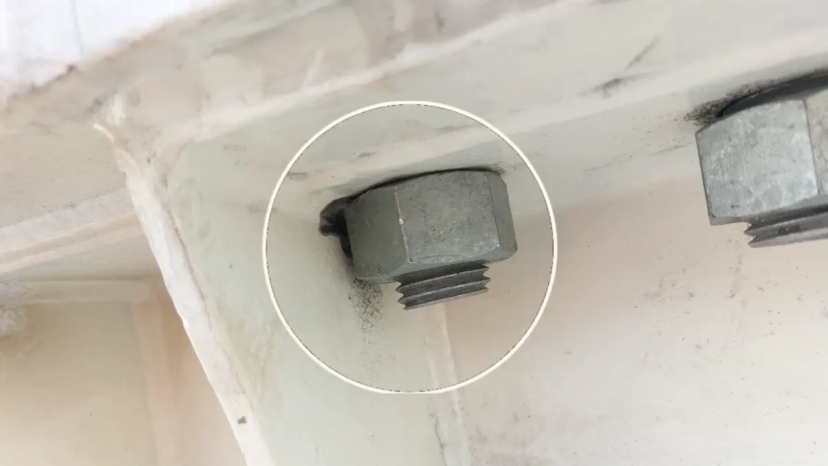
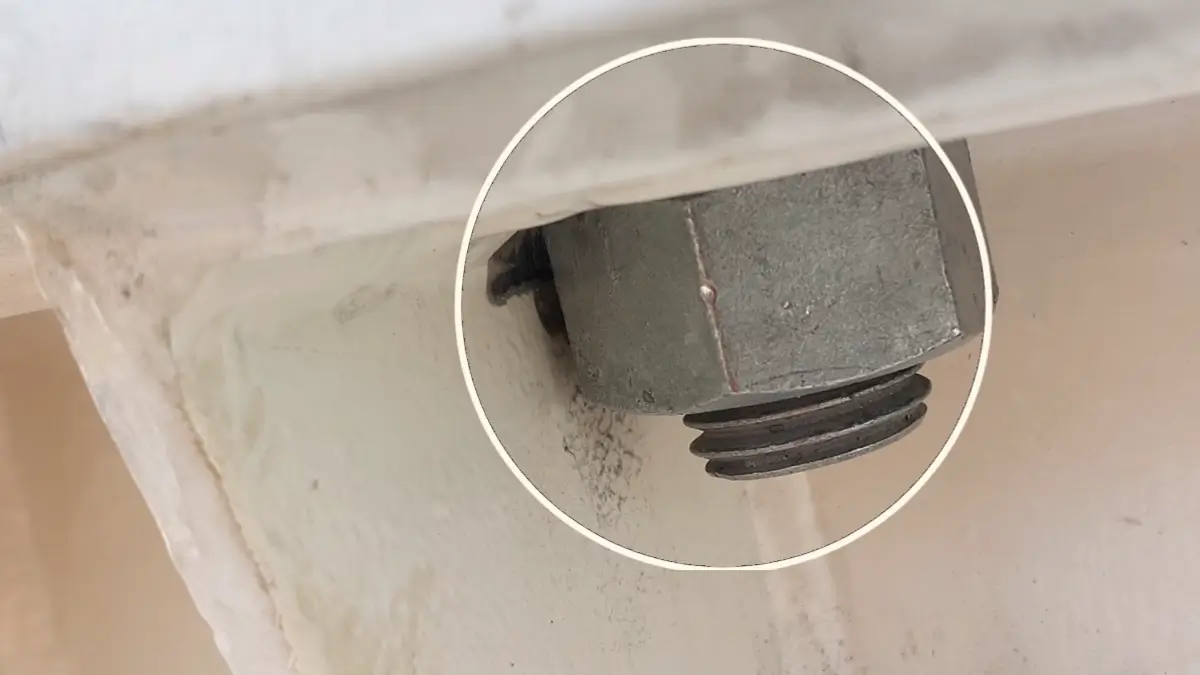
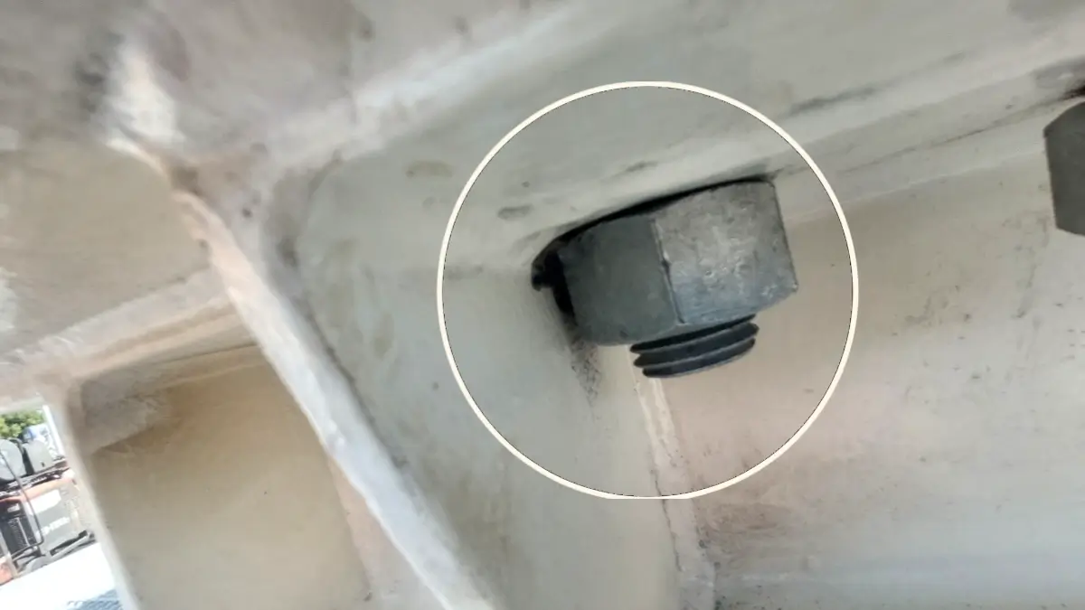
Close-up of motor base bolt clearance that may restrict accurate laser alignment.
Limited motor base bolt clearance can prevent precise laser alignment.

Detailed view of the motor base and mounting bolts, highlighting insufficient bolt clearance. This condition can limit motor movement during alignment and make laser alignment errors difficult to identify.

Improper Motor Base Bolt Clearance: Hidden Laser Alignment Problem

Case Study: Nut Contact With Base Frame Wall Affecting Alignment Repeatability

During precision laser shaft alignment, achieving the correct laser measurement is only part of the job. The motor and pump must also be mechanically installed so that the equipment can be tightened, supported, and maintained in a stable and repeatable condition. The attached photograph shows an important installation problem found underneath a motor base frame.

The nut used to secure the motor base to the base frame was positioned too close to the side wall of the base frame. This restricted the available clearance around the nut and created a potential problem during bolt tightening. Such a condition can affect the final mounting position of the motor and may result in changes to alignment readings when the mounting bolts are tightened or retightened.

The Problem: Restricted Nut Clearance

The motor base was mounted on the base frame with the use of a bolt and nut combination. But upon checking, it was found out that the nut was very near the side wall of the base frame. The clearance space was not enough for a proper tightening process. This is a condition that is often overlooked since the installation of the bolt and nut appears to be okay from the top of the equipment. But the installation of the nut beneath the base frame is just as important. There should be enough clearance for the proper tightening and seating of the nut. Otherwise, the tightening process will be inconsistent.

Why This Matters During Laser Alignment

Laser alignment depends on the real mechanical position of the machine. In case the bolts that hold the motor are not properly tightened, the motor will not be in the same position once the final tightening is done. This poses a very serious challenge to precision alignment.

For example:

Initial alignment → Tightening of bolts → Motor shifts → Alignment changes

The alignment could be right prior to the final tightening, but once the motor shifts due to tightening of bolts, there will be changes in the final shaft alignment. The same applies when rechecking the alignment and mounting condition.

Possible Effect on Alignment and Mounting

In case there is insufficient clearance of the nut, some issues may arise. For example, the bolt may fail to be tightened properly. Uneven contact or interference in the tightening area could also happen. In case of welding spatters, burrs, dirt, and/or rough surfaces on the seating area of the nut, the nut may fail to seat properly. This would mean that the clamping condition would not be consistent. If the mounting condition varies, then the position of the motor will vary. Thus, the end results:

– Horizontal alignment
– Vertical alignment
– Motor position
– Shimming requirements
– Mounting stability
– Alignment repeatability

would be affected.

Welding Burrs and Uneven Surfaces

Base frames that are fabricated will always have welds at the mounting points. After fabrication and welding, one has to examine the mounting and tightening points. Welding burrs, weld spatter, sharp edges, dirt, or an uneven surface might hinder the seating of the washer or nut. A slight obstacle might prevent the fastener from getting into the clamping position. It is for this reason that the mounting point has to be examined and cleaned before conducting laser alignment. This is with the aim of ensuring that the tightening position is clean, smooth, accessible, and mechanically sound.

Don’t Align Against a Loose or Unstable Mounting Condition

Motor mounting bolts with restricted clearance during laser alignment.
Restricted bolt clearance is a commonly overlooked cause of laser alignment issues.

Close-up detail of the motor mounting area where bolt clearance is limited. Insufficient clearance can restrict adjustment of the motor base, potentially resulting in alignment problems that are not immediately visible during laser alignment checks.

A precision laser alignment system can give highly precise measurements. However, the laser cannot compensate for any mechanical issue that may exist during installation. In case the bolt of the motor base cannot be tightened, the final measurement of the alignment will not be an accurate indication of the machine’s real position. This is why alignment engineers must check the entire installation setup before making final adjustments. The right process must be:

Check → Clean → Verify clearance → Tighten properly → Measure → Adjust → Recheck

What Should Be Checked Before Laser Alignment?

Before initiating the final laser alignment of the pump-motor, the motor mounting structure must be examined.

Important examinations include:

1. Clearance of Nut and Bolt: Check whether the clearance between the nut and bolt is adequate for tightening.

2. Washer Alignment: Ensure that the washer is correctly seated and properly contacting the mounting surface.

3. Welding Spatter and Burrs: Remove all welding spatters, burrs, and other obstacles from the tightening area.

4. Cleaning of the Mounting Surfaces: Clean the mounting surfaces of dust, rust, paint deposits, oil, dirt, and other contaminants.

5. Base Frame Condition: Ensure that the fabricated base frame does not hinder the bolt, nut, washer, and motor foot.

6. Motor Feet Contact: Check if the motor feet are appropriately resting.

7. Final Bolt Tightening: Confirm that the mounting bolts can be tightened correctly according to the approved torque procedure.

8. Alignment Recheck: After corrections and making tightening, perform another laser measurement to verify that the machine position has not changed unexpectedly.

Clean and Free Conditions Are Essential

For accurate positioning, the mounting must be as loose and clean as possible.

The following should not happen:

– The nut should not touch the wall of the base frame
– The Washer should not touch the wall of the base frame
– Interference from the bolt
– Welding spurs
– Welding splashes
– Unlevel tightening surfaces
– Dirt on the contact surfaces
– Broken washers
– Inappropriate placement of shims
– Restricted access for tightening

While these might seem like minor issues during fabrication and installation, they may have an effect on the mechanical condition of the machine.

The Importance of Alignment Repeatability

An ideal alignment must be repeatable. Where the alignment readings vary considerably each time the mounting bolts are loosened and tightened, the solution should not just be seen as a matter of aligning the motor. The mounting should be examined for its cause. This could be due to:

– Tightening of bolts
– Nut clearance
– Shimming
– Poor foot contact
– Base frame issues
– Contamination
– Welding deformation
– Uneven mounting surface

Correcting the mechanical cause is better than re-aligning the motor.

Conclusion

Motor base bolt and nut touching the base frame wall during laser alignment inspection
Improper motor base bolt clearance can create a hidden laser alignment problem.

Close-up view of motor base bolts showing inadequate clearance around the motor base. The restricted clearance can interfere with proper motor positioning and contribute to a hidden laser alignment problem.

This picture shows one of the small details that could be easily missed when installing the pump and motor. The nut under the motor base was placed very close to the side wall of the base frame, leaving little room for tightening. If the bolt and nut cannot be tightened to the desired position, then the motor mounting might not be stable or repeatable. Welding burrs, spatter, and an uneven surface for tightening will make it even more difficult for the bolt to seat properly. For laser alignment, the mounting configuration should be checked prior to alignment.

Make the mounting area free, clean, smooth, and accessible. Confirm proper bolt and nut clearance. Tighten correctly. Then perform the laser alignment and verify the final result after tightening. A precision laser alignment is only as reliable as the mechanical condition of the machine being aligned.

Key Takeaway

Prior to laser alignment, one should not only verify the shafts but rather all components securing the machine into place. Correct bolt clearance, clean mounting surfaces, correct shimming, correct seating, and correct tightness are important to achieve the desired alignment result.